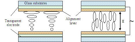
![]() |
|
|
Switchable Polarization rotator
Liquid Crystal twisted nematic polarization rotator (TN cell) is very useful when one wants to rotate the orientation of a linear polarization by a fix amount of typically 45° or 90°. When light is traversing LC twisted nematic cell its polarization follows the rotation of the molecules (see figure below). The screens of any laptop computer is based on the same effect (polarization rotator tutorial). In optical systems the polarization is often rotated by quartz retardation plates (l/2 or l/4 plates). Quartz plates shows high quality and good transmission performances especially in the UV region. However such plates present also some disadvantages: They are expensive, functions only for a narrow spectral bandwidth and have a small incidence angle acceptance (field of view less then 2°). The liquid crystal nematic cells have therefore a large acceptance angle, function over a very large spectral range from VIS to NIR (if they are thick enough) and are less expensive. Optionally, by applying a voltage on the TN cell, the polarization rotation can be switched off. Also when placing a 90° twisted cell between crossed polarizers it can be used as a shutter. l/2 plate for a very broadband range of wavelengths
Optionally rotation effect can be electrically switched off
In combination with two crossed polarizers it can be used as an optical shutter
Polarization Rotators Type
Specificities
Applications
Price
Industrial grade
Spacer (few microns) over
the aperture
Large aperture (22mm)
Thin substrates
Phase distortions (spherical)
Low beam deviation Polarization manag.
Polarization vision**
Scientific grade
Low phase distortions
No beam deviation
No spacers over the
aperture
Aperture 10mm or 20mm
Thick substrates
Broadband AR coating Interferometry
Metrology
Use in an imaging
plane colimated laser beam
***
Custom
Larger apertures.
High switching speeds.
Large quantities/low price.
Zero phase shiftCustom adapted cells
for industrial
applications
Specific scientific
applications* / ****
For more information please download the product description PDF file in the tabs below or contact Arcoptix: info@arcoptix.com
A twisted nematic liquid crystal cell consists essentially of a liquid crystal layer placed between two treated glass substrates.
The inner-surfaces of the cell is composed of two layers: The first layer is a transparent electrode (mostly ITO). It permits to apply an electrical field across the cell and switch the cell between the OFF and the ON state. The second layer is responsible for the homogenous alignment of the LC. It is generally a rubbed polyimide layer of about 100nm.
The liquid crystal alignment at both sides of the cell is hence defined during cell manufacturing. By careful control, any twist-angle can therefore be induced in the helical structure across the liquid crystal layer. With a twist-angle of exactly 90°, the standard 90° twisted nematic (TN) cell is formed. Twist-angles of less than 90° form the low-twist (LT) cell whereas by definition, super-twist cells are cells that possess twist-angles exceeding 180°.
The two glass substrates are separated by spacers with a well defined size (usually between 3mm and 20mm) and sealed with glue.
When the polarization rotator is in the off state, the helical structure formed by the LC molecules rotates the entrance polarization as shown in figure 1. In the ON state the polarization rotary power is suspended and the polarization state of the light entering normally to the entrance surface is not altered by the TN cell.
100% efficient rotation of a linear entrance polarization can only be obtained in the limit of large cell thickness and in general the exiting light becomes elliptically polarized with components oscillating in directions lying both parallel and perpendicular to the exit liquid crystal molecules. Furthermore, it is the optical-path-difference in the liquid crystal cell that affects the overall magnitude of the polarization efficiency for the TN cell. The optical-path-difference is given by the Dnd parameter, where Dn is the anisotropic index of refraction for the liquid crystal material and d is the cell-gap. The following equation shows the transmission of a TN 90° cell as function of a normalized retardation parameter u. It assumes that the TN cell is placed between two parallel orientated ideal polarizers.
![]()
The best extinction (which means also the best rotation efficiency) is obtained with the highest optical path difference. So for optimal rotation of the entrance polarization over a broad spectral range it is better to use a TN cell with a high optical path difference (which means a large cell gap and a high anisotropy).
However one must be aware that higher cell gaps decrease drastically the switching time of the TN cell. So rapid switching times and high efficiency over a brad spectral range cannot be obtained. Notice that the curves shows some minimum and a custom made TN cell can be optimized to have a good rotatory efficiency (low transmission) and a rapid switching time (minimal cell gap) for a narrow range of wavelength .
In application where switching time does not matter it is better to choose a TN cell with a high optical path difference.
Specifications
The table below summarizes the principal characteristics of the device:
Rotation angle
90° or 45° (custom any angle possible for scientific and industrial grade)
wavelength range
350-1700 nm
Active area
scientific grade:10 mm or 20 mm (diam.)
Industrial grade:22 mm (square)Transmission
About 85% (VIS)
Retarder material
Nematic Liquid-Crystal Dn=0.28
Substrates
Glass
wavefront distortion
scientific grade:
< lamda/4 (over 10 mm)
Industrial grade:
< 2lamda (over 23 mm)temperature range
15°-35°
Rotation accuracy
+/-1° (wavelength dependent)
Maximum modulation frequency of the phase shift
< 10Hz
Save operating limit 500 W/cm2 CW
300 mJ/cm2 10 ns, visible
200 mJ/cm2 10 ns, 1064 nmAnti-reflection coating (scientific grade only)
Broadband for VIS.
Total size (with housing)
Scientific grade: 25 mm diameter, 15mm long
Industrial grade: 31mmx25mmx2.2mm (without housing).
Driver (optional)
The Polarization rotator can be driven with a standard labor function generators but it can also be driven by the USB ARCoptix LC Driver.
The Arcoptix LC (Liquid Crystal) driver is a USB computer controlled electrical power supply optimized for driving one or two Polarization rotators.
The LC driver has two independent outputs (Lemo connectors). They are controlled via a simple windows compatible software. The output has a variable square amplitude with polarity inversion and a frequency of 1.6 KHz. This guarantees a homogenous variation of the LC layer inside the cell. An external trigger input can be provided on demand.
Prices
Devices
Prices
Industrial grade 45° or 90° (23mm ap. without housing)
390 Euro
Scientific grade any angle (10mm ap.with housing)
790 Euro
Scientific grade (20mm ap.with housing) 1190 Euro USB LC Driver (2 outputs) 590 Euro
For custom models please contact info@arcoptix.com for quotation.